Heat flux measurement techniques: a comprehensive overview
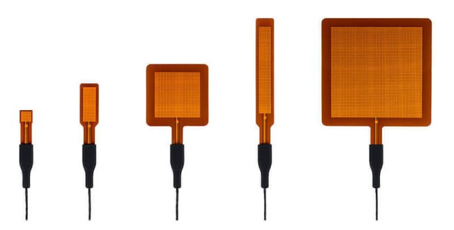
This article focuses on heat flux measurement techniques. We will explain how heat flux measurement works by using foil heat flux sensors. We will specifically zoom in on the heat flux sensors of Hukseflux, the FHF05 series; a series of sensors with models in five different dimensions. They are all equipped with spreaders; a thin metal foil covering the sensor.
First, we briefly explain why heat flux measurements are so important and how heat flux sensors work. Then, we discuss two beneficial technical features of the FHF05 series. After that, we highlight four advantages of the FHF05 series over other heat flux sensors available on the market. Finally, we assist you in selecting the appropriate heat flux sensor for your application.
Heat flux measurements
Heat flux comes in three types: radiation, convection, or conduction. All three are mechanisms to transport heat. The total heat flux is the sum of these three types.
Heat flux measurements provide unique information that complements temperature measurement. Measuring both, you can, for example, measure the insulation values of walls, or heat loss in pipes or tubes. This information can also be used to learn more about cooling mechanisms in electronics. Knowing where heat is lost or gained can help you make your system more energy-efficient.
How does a heat flux sensor work?
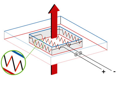
heat flux sensor with thermopiles.
To measure heat flux, you need a heat flux sensor. A heat flux sensor measures a small temperature difference across a thin layer of material. This material typically employs a thermopile. A thermopile is an alternating pattern of two dissimilar metal alloys. Schematically, this looks as follows, see Figure 1.
In Figure 1 you can see a heat flux sensor with the sensitive surface at the center. If you look at the enlarged view, you can see the two metal alloys in alternating patterns. When energy flows through the centre, these metal alloys will generate a small voltage. This small voltage output can be read out and directly translated into a value of the energy stream: the heat flux.
At Hukseflux, we offer a broad product range of heat flux sensors in different sizes and shapes. There are, for example, heat flux sensors that can be used for certain temperature ranges and heat flux sensors that can be used for certain heat flux ranges.
This article focuses on the Hukseflux FHF05 series heat flux sensors. These are used for general-purpose heat flux measurements. Their design and manufacturing is based on a patented technology. Based on this design, Hukseflux developed a durable, stable and reliable sensor which has many advantages over competing sensors.
Technical Features
To ensure we can offer a reliable sensor that is also robust, the Hukseflux FHF05 series has multiple technical features. The two most important features are the cable connection and the integrated temperature sensor.
Cable connection
Small voltages are generated by a heat flux. The output needs to be read out using a cable. This cable connection is designed to be robust. A well-designed cable connection provides strain relief and will also protect against humidity ingression (IP67 classification).
Integrated temperature sensor
The second technical feature of the Hukseflux FHF05 series heat flux sensors, is the integrated temperature sensor. Below the sensitive surface, there is an integrated type-T thermocouple. Using the thermocouple, you can perform a temperature measurement simultaneously with the heat flux measurement. This will give you more information about the energy balance at your measurement location. Both the measurement of the temperature and the heat flux are passive, which means that they do not require power.
Advantages of FHF05 series heat flux sensors
The Hukseflux FHF05 series heat flux sensors offer many advantages over competing sensors. These advantages lead to more accurate measurements. Listed below are four advantages; very robust, highly flexible, low thermal resistance and low thermal conductivity dependence.
Very robust
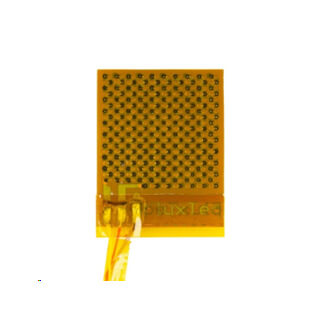
As said before, the cable connection of our FHF05 series heat flux sensors is created to be robust. Other suppliers chose different cable connections. In Figure 2 you can see an example of a sensor that is easily damaged; the connection method wire to sensor is very vulnerable. You can also see open traces. Because of this, the small voltages generated by the heat flux will get easily distorted by sources in the environment. Besides, the connection method is not waterproof. This cable connection solution may result in serious corrosion and stability issues. Last but not least, the connection is mechanically very vulnerable. Put a small strain on the wires and they will tear off.
Highly flexible
The patented technology of the FHF05 series ensures a very flexible sensor that still performs stable measurements when bent to a radius of 7.5 mm. This flexibility is required when measuring on curved surfaces like pipes or tubes. This is a major advantage relative to other sensors that are not flexible at all. Evidently, these are not suitable for measuring on curved surfaces.
Other suppliers do offer flexible sensors, but those are not always stable when bent. Unstable means that the sensitivity changes. This instability can be tested by measuring the electrical resistance with a resistance meter.
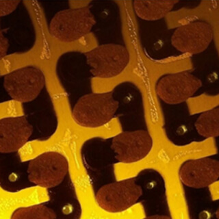
of a sensor from another supplier.
For example, sensors from other suppliers are sometimes made of metal-filled inks. Figure 3 shows an image made with a microscope. Looking closely, you can see the individual metal particles. When you bend the sensor foil, the connection between these particles loosens or even breaks, causing changes in the electrical properties. That is what can be measured with the resistance meter. The sensor is not stable and, in some cases, even permanently damaged.
All in all, this sensor will have serious stability issues when being bent. The technology of FHF05 series on the other hand, is designed to be flexible as well as stable, which ensures accurate results, even on curved surfaces.
Low thermal resistance
When mounted on a surface, a heat flux sensor always adds a layer of thermal resistance. Moreover, depending on the material type surrounding the heat flux sensor, the sensor may locally increase or decrease the thermal resistance. But how do these factors affect the heat flux measurement?
Heat always tends to follow the easiest path. Suppose you have a heat flux sensor with a lower thermal resistance than its environment; the easiest path will be towards the heat flux sensor. Schematically, this will look as follows:
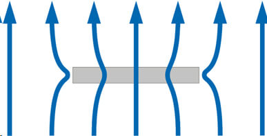
with a lower thermal resistance than its environment.
The grey area represents the sensor, and the blue arrows
represent the heat flux field.
The measurement result is now an overestimation of the actual, undisturbed heat flux. If we now take a closer look at the situation where the sensor has a higher thermal resistance compared to its environment, the following will happen:
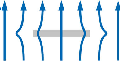
with a higher thermal resistance than its environment.
The grey area represents the sensor, and the blue arrows
represent the heat flux field.
Again, heat always tends to follow the easiest path. In this case, the easiest path will be around the heat flux sensor. The sensor will measure an underestimation of the actual (undisturbed) heat flow.
To prevent measurement errors caused by thermal resistance, the FHF05 series sensors are designed to be thin and well-conducting. This ensures that the sensors have a high thermal conductivity, which minimises any disruption to the heat flow when placed on a surface. Schematically this will look as follows:
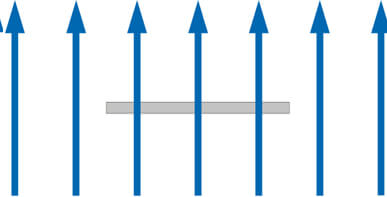
of a high-thermal-conductivity material, which means they disturb
the heat flux field as minimally as possible.
Low thermal conductivity dependence
The FHF05 series has a low thermal conductivity dependence. In other words, the sensitivity does not depend on the thermal conductivity of the material on which it is installed. How does this work?
As illustrated in Figure 7, a heat flux sensor can have no spreaders (left), in which case the individual thermopiles are exposed to the environment, one with a single large spreader (middle) and one with multiple small spreaders (right).

Right: a sensor with multiple small spreaders.
To explain why spreaders cause the FHF05 series to have a low thermal conductivity dependence, let's zoom in on the sensor, as shown in Figure 8, and focus on microscopic effects.
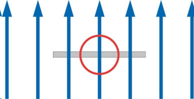
we zoom in on a section of the heat flux sensor.
In the situation where you have no spreaders, two things can happen. First, the thermopile of the heat flux sensor can have a higher thermal conductivity compared to its environment. In this situation, the sensor will measure an underestimation of the heat flow, as depicted in Figure 9a.
On the other hand, the sensor can have a lower thermal conductivity compared to its environment. In this situation, the path through the thermopile is easy for the heat flow; therefore, more heat travels through the thermocouple, as depicted in Figure 9b. The sensor will now overestimate the actual heat flux. In this situation, the sensor is dependent on the thermal conductivity of its surroundings.
If a heat flux sensor is covered with a spreader, which is a thin layer of metal foil, the heat will be distributed evenly among the thermopile, as depicted in Figure 9c. The thin metal foil will spread out the heat, and the thermopiles will only sense the spreaders. As a result, the measured heat flux will be accurate.

The thermopiles don't measure all the heat flux.
Middle: sensor with no spreaders and a lower thermal conductivity than its surroundings.
The thermopiles overestimate the actual heat flux.
Right: sensor with thermal spreaders. The spreader conducts all heat in-plane,
creating a constant environment for the thermopile.
Thermal conductivity dependence – tests
This concept of thermal conductivity dependence has been tested at Hukseflux, resulting in the following graph.
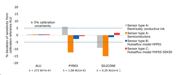
What you can see here, are four sensors that were tested. The grey and orange bars represent heat flux sensors without spreaders. The blue and red bars represent heat flux sensors with one large, and the other multiple small spreaders, respectively. The sensor type C is part of the Hukseflux FHF05 series.
In the test, three different materials were used, represented on the x-axis. The first material is aluminium. This is considered the benchmark situation since an aluminium heat sink is used in Hukseflux’s calibration facility. The second material is Pyrex, which is comparable to glass. The last material is silicone, which is a typical plastic. The three materials have a different thermal conductivity, represented by the constant λ.
On the y-axis, the percentage deviation relative to the benchmark situation is plotted. The blue dotted line indicates the uncertainty of the test method, which is 5 %.
If we now take a closer look at what happens with Pyrex, the sensors without spreaders show large deviations; larger than the uncertainty of the test setup. The two Hukseflux sensors show deviations within this uncertainty. The same is visible for silicone, there are large deviations for the sensors with no spreaders and deviations within the calibration uncertainty for the sensors with spreaders.
We can conclude that the sensitivity of heat flux sensors with spreaders does not depend on the material on which it is installed. This gives more accurate results than sensors of other types.
FHF05 series – Select your model
FHF05 series heat flux sensors are available in five different dimensions. This step-by-step plan will help you select the right sensor for your application and electronics.
- Verify that the FHF05 series is suitable for your application.
- the heat flux is between (-10 to +10) × 103 W/m2
- the rated temperature range is below 120 °C
- Verify what sizes may be used.
- define a maximum sensor size
- see which model fits
- Determine if you want to separate radiation and convection in your measurement.
- Estimate the output range of the heat flux sensor(s) in [× 10-6 V] using the sensitivities in the specifications table on our website. The microvolt output range = heat flux range in [W/m²] x sensitivity in [x 10⁻⁶ V/(W/m²)].
- Verify that your electronics are suitable for the measurement.
- they have to accept analogue voltage differential input
- the microvolt voltage measurement accuracy is better than 1 % of the output range. If not, this can be the limiting factor in measurement accuracy
- your electronics accept type T thermocouples. If this is not the case, consider whether a temperature measurement is necessary or if a separate temperature sensor can be added
In case you need a flexible, thin and versatile heat flux sensor that can withstand temperatures of up to 250 °C, you can have a look at our FHF06 heat flux sensor.
If you need help selecting the right sensor for your application, please contact us.


