How to measure albedo, best practices
The measurement of albedo is becoming more popular with the increasing demand for solar energy.
This article discusses how to measure albedo. First, we describe the quantity albedo and explain what an albedometer is. Second, we describe how an albedometer measurement of a limited area can be made at a distance close to the ground surface. Such areas are also known as “finite samples”.
Right after, we describe the main application of albedo measurement: the performance assessment of bifacial PV modules. Since these modules are often mounted close to the ground surface, the theory discussed earlier comes in handy. The best practices for this application, as recommended by IEC 61724-1, and the best general practices given by ISO/TR 9901 are referenced throughout this article. Finally, we discuss what kind of albedometers Hukseflux has to offer.
Measure albedo with an albedometer
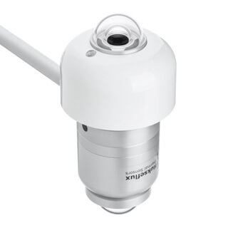
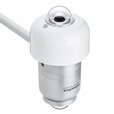
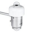
two SR30 pyranometers.
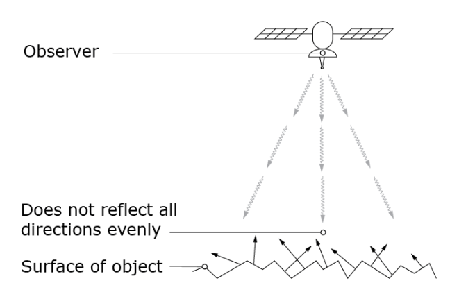
As discussed in the article What is albedo?, albedo is the ratio of the reflected to the global radiation. It is represented by a dimensionless number between 0 and 1, where 0 means that all sunlight is absorbed and 1 means that all sunlight is reflected. Albedos of typical surfaces range from about 0.15 for green grass to 0.90 for fresh snow.
An albedometer is a device that measures the albedo of a surface. It consists of two pyranometers. One faces upwards to the sky, and the other faces downwards to the surface. The albedo can be calculated by measuring the direct irradiance with the upfacing pyranometer and the reflected irradiance with the downfacing pyranometer. To learn more about pyranometers, please read the article Pyranometers – All you need to know.
Albedometers are used for multiple purposes. Historically, they are used for meteorological observations and climate research. However, measurements of small areas of ground surface have gained popularity over the past years. This is due to the increasing demand for PV modules; more on this later. First, we explain how to measure the albedo of finite samples.
Measuring albedo of finite samples
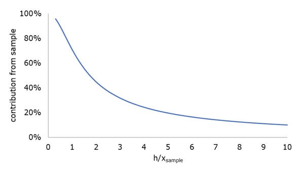
to the total reflected irradiance as a function of h/xsample.
When measuring the albedo of a small surface area, it is important to keep a few things in mind to get an accurate result.
First, according to the ISO/TR 9901 standards, the mounting device should be designed to minimise reflections or shadows in the field of view of the albedometers. To reduce shading, non-reflective paint is used on the masts of mounting devices. Moreover, the pyranometers are mounted on devices extending toward the equator to minimise reflections.
Second, the ISO/TR 9901 standard requires the ground beneath the downfacing pyranometer to represent the surrounding area. Finally, errors in the shading of direct solar radiation by the sensor on the sample should be minimised. The installation height is a trade-off between these two considerations.
Let’s consider a downfacing pyranometer positioned h meter above a sample to optimise the installation height. The sample has a radius of Xsample meter. A part of the reflected irradiance comes from the sample. However, the rest of the reflected irradiance is from the surroundings. The relative contribution of the sample to the reflected irradiance measured by the pyranometer is plotted in Figure 2. On the horizontal axis, h/Xsample is placed.
Considering this graph would make things easy, the pyranometer should be positioned as close to the ground area as possible to get the highest contribution of the sample. However, mounting an albedometer close to the surface causes the sensor itself to shade the sample by direct solar radiation.
The size of the shadow depends on the diameter d of the pyranometer. The table below lists the diameter of three albedometers offered by Hukseflux.
Table 1 Diameters of three Hukseflux albedometers.
| Albedometer | Diameter [m] |
| SRA20 | 0.15 |
| SRA 20 without sunscreen | 0.078 |
| SRA01 | 0.066 |
The position of the shadow depends on the installation height h and the solar zenith angle. This angle is the angle between the rays of the sun and the vertical.
Let’s consider a zenith angle of 10 °. The measurement error due to shading as a function of installation height for this angle is plotted in Figure 3. This relationship is plotted for the three albedometers listed in Table 1.
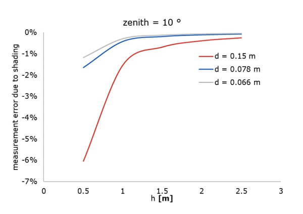
diameters given in Table 1 at a zenith angle of 10 °.
This graph shows that the measurement error decreases as the installation height increases. Below an installation height of 1 meter, the measurement error increases rapidly.
To conclude, as the installation height of an albedometer is lowered, the measurement of the sample is getting more representative. However, if the sensor is installed too low, significant measurement errors occur due to shading. The ISO/TR 9901 standard recommends an installation height between 1.5 and 2 meters above the ground. An advantageous side effect of this installation height is ease of maintenance.
An important application of an albedo measurement of finite samples is the performance monitoring of bifacial PV modules. Before discussing the performance model and recommendations for such systems, we explain what bifacial PV modules are.
What are bifacial PV modules?
Photovoltaic power stations (PV systems) are composed of multiple solar panels. Each solar panel contains photovoltaic cells assembled in PV modules. These modules convert solar energy into electricity.
A PV module can be mono-facial (single-sided) or bifacial (double-sided). The back of a single-sided PV module is coated with metal, whereas the back of a bifacial module has a glass panel. Therefore, the bifacial PV module can collect light and generate electricity from both sides.
For single-sided PV modules, the contribution of the albedo effect to energy production is insignificant and often neglected. However, the albedo effect must be considered for bifacial modules since the backside can produce 10-25% of the total energy. Multiple factors are important when considering the increase in energy production—for example, the spacing and the reflectance of the surface in a PV system.
The following section describes the best practices for measuring the albedo in PV modules.
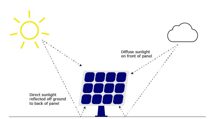
Measuring albedo for bifacial PV
When measuring the albedo of PV modules, which performance model is used must be clear. There are different types of performance models. IEC defines a performance model as “a mathematical description of the output of a PV system as a function of meteorological conditions, the system components, and the system design”. Some performance models require the albedo as ground surface property. Other models use the reflected irradiance as input for the albedo. Stakeholders agree upon the performance model before measurements take place.
To calculate the albedo of bifacial PV modules, most performance models require the following parameters:
- The Plane of Array (POA) radiation. The POA is the amount of sunlight collected at a given panel orientation. This can be measured with the upfacing pyranometer that operates in the Plane of Array. Another possibility is that it is estimated from the Global Horizontal Irradiance (GHI).
- The horizontal reflected irradiance (HRI). This can be measured with the downfacing pyranometer.
- Some performance models require distributed sensors or site surveys to understand the spatial variability of the albedo better. It is necessary to measure the variability of the albedo to evaluate uncertainty properly, as required by the IEC.
Bifacial PV module complications
A finite sample’s albedo can be considered a property of the ground surface. This is under the assumption that the ground surface is representative of its surroundings.
However, for bifacial PV systems, complications occur. For example, the shading of the ground surface by the solar panels and the albedo of the ground surface dominate the amount of reflected irradiance between PV arrays. Moreover, the shading and ground surface properties are not homogeneous for the total area.
Besides these complications, the ratio between the reflected radiation below the solar panels and the total global horizontal irradiance above the solar panels varies widely:
- The reflected solar radiation beneath the solar panels varies in space over a power plant. Due to different shading patterns, the albedo in the middle of a row of solar panels is different from that at the end of the row.
- The reflected solar radiation beneath the solar panels varies over the day. This is due to moving local shading patterns.
- The albedo of the ground surface varies seasonally. The albedo can be influenced by the type of vegetation present and the soil's moisture level.
Best practices in albedo measurement
Because of all the complications mentioned, the recommendation for albedo measurements for bifacial is to keep things as simple as possible.
The IEC 61724 standards recommend:
- Keep the albedo definition simple: most models assume albedo is a ground surface property with monthly variability. The performance model handles corrections for shading and Plane of Array (POA).
- One instrument should be used away from the array to obtain an unobstructed reference albedo measurement.
- To simplify logistics, using the same instruments for measuring POA, GHI, and RI is recommended.
- Perform surveys in different seasons to determine surface properties. This includes a comparison with an unobstructed reference station.
- At the location of all POA measurements, a measurement of the local albedo is required. First, this is to verify that the albedo represents the total power plant. Second, in this way, it can be checked that the measurements fit the assumptions made in the modelling. Finally, the local albedo can be used for the uncertainty evaluation of the performance test.
Albedometers offered by Hukseflux
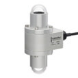
Hukseflux offers different sensors for albedo measurements. In the table below, the main models are compared.
Table 2 Comparison of the albedometers offered by Hukseflux.
Spectrally flat Class A pyranometers typically measure POA, GHI, and RI. Using the same instruments for measurements on PV systems is recommended to simplify data acquisition.
It can be considered to use multiple instruments between rows to verify model calculations of reflected irradiance. Moreover, spatial variability can be analysed in this way. Lower accuracy instruments (spectrally flat class B or C) may be used for this type of calculation.
Hukseflux is always ready to help you if you are still deciding. Just contact us, and our experts will give you free personal advice!


