


 Understanding the energy balance of the earth's surface is important as it plays a significant role in processes such as climate dynamics, weather patterns, and ecosystem functioning. Net radiation determines whether a specific area gains or loses heat over time.
This article discusses the NR01, a net radiometer providing four separate measurements of global and reflected solar, downwelling, and upwelling longwave radiation. The article covers how the solar radiation measuring device is built up, installed and calibrated, how the data is processed, and finally, how the quality of the data is controlled.
What is net radiation?
The earth's net radiation, or net flux, is the balance between incoming and outgoing energy at the ground surface. It represents the total energy available to influence the climate. Solar energy enters the system and eventually exits through two routes: reflection and thermal radiation, which is the heat emitted by the atmosphere and surface, including clouds. Meanwhile, the net solar and infra-red energy, net radiation, is the power source behind wind, evaporation, ocean currents, etc.
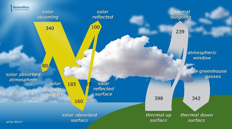
Qualitatively, the net radiation can be described by the formula:
Net radiation = Incoming shortwave radiation + Incoming longwave
Radiation - Outgoing shortwave radiation – Outgoing
longwave radiation
Shortwave radiation consists of electromagnetic waves with relatively short wavelengths, primarily in the range of ultraviolet (UV), visible, and near-infrared (NIR) regions of the spectrum. On the other hand, longwave radiation consists of electromagnetic waves with longer wavelengths, primarily in the range of invisible thermal infrared radiation.
The global average of net radiation should be approximately zero throughout the year, or otherwise the planet's average temperature will increase or decrease. Locally, however, we expect yearly average shortages or surpluses. Also, daily or seasonal effects are of interest for a better understanding of meteorological processes.
Net radiation measurement
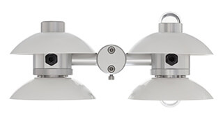
A net radiometer, such as the NR01 in Figure 2, measures net radiation. This device comprises four primary components, two pyranometers and two pyrgeometers, each corresponding to a specific quantity of the net radiation equation.
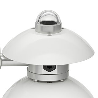
On the right side, the two pyranometers are installed. The up-facing pyranometer measures the global solar radiation (Eg↓h), while the down-facing pyranometer measures the reflected solar radiation (Er↑).
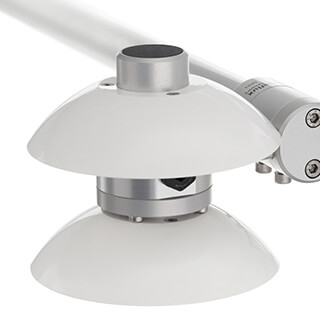
On the left side, the two pyrgeometers are mounted. The up-facing pyrgeometer measures the downward longwave radiation (El↓), and the down-facing pyrgeometer measures the upward longwave radiation (El↑).
We can now rewrite the earlier qualitative equation into a quantitative equation using the notations introduced above:
E = Eg↓h + El↓ - Er↑ - El↑
The pyranometers are SR01 models, and the pyrgeometers are IR01 models. Besides these four sensors, the NR01 contains a Pt100 temperature sensor and a heater. We will now describe each component in more detail.
SR01 pyranometers
The two SR01 pyranometers used in the NR01 are black-coated thermopile detectors under glass domes. A thermopile detector is an infrared sensor used to measure the intensity of infrared radiation. The glass dome transmits shortwave radiation and blocks longwave radiation. The transmitted radiation is absorbed by the coating, thereby heating the coating. This creates a temperature difference over the thermopile. The thermopile generates a small voltage proportional to this temperature difference.
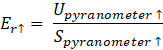
As mentioned before, the SR01 pyranometer is responsible for measuring the incoming and outgoing shortwave radiation. This is done by dividing the voltage output (U) by the sensitivity of the sensor (S). For example, for the up-facing pyranometer, the shortwave radiation is determined using the formula:
IR01 pyrgeometer
Two pyrgeometers of model IR01 are situated on the other side of the NR01. These devices use a measuring principle that is very similar to the SR01 pyranometer.
The IR01 pyrgeometer has a black-coated thermopile detector, much like the SR01. However, unlike the SR01, the sensor of the IR01 is located under a silicon window with a solar blind filter. The silicon window allows the transmission of longwave radiation while blocking shortwave radiation. The coating absorbs the transmitted radiation, creating a temperature difference over the thermopile. This temperature difference generates a small voltage proportional to the amount of radiation absorbed.
The longwave radiation is again determined by dividing the voltage output (U) by the sensitivity (S) of the pyrgeometer. However, there is another term that depends on the Stefan-Boltzmann constant 𝜎 and the temperature T of the surroundings: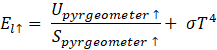
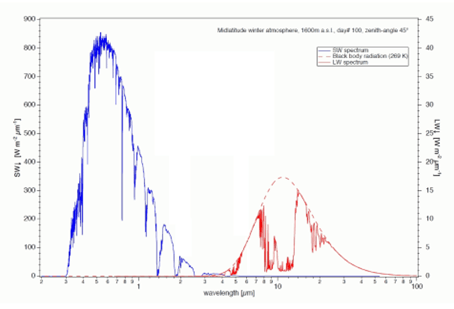
The graph presented in Figure 5 shows the spectrum of sunlight. The blue curve represents the shortwave radiation, while the red curve represents the longwave thermal radiation. As mentioned earlier, the pyranometer glass dome allows the transmission of shortwave radiation and blocks longwave radiation. The silicon window of the pyrgeometer does the opposite. Therefore, the pyranometer's response is represented by the blue curve, while the red curve represents the pyrgeometer's response.
Pt100 sensor and heater
Besides two pyranometers and two pyrgeometers, the NR01 also contains a Pt100 platinum resistance temperature detector located between the two pyrgeometers. Instead of measuring the temperature directly, the resistance of the platinum detector is measured, from which the temperature can be derived. However, this measurement is unnecessary for net radiation measurement, because the instrument temperature does not affect the net radiation equation.
In addition to this Pt100 sensor, there is also an electrical heater inside the instrument, which generates 1.5 watts of power when 12 DC voltage is applied. The heater is located between the two pyrgeometers, which aims to heat the instrument. By doing so, dew and frost can be reduced by raising the instrument temperature slightly above the dew point temperature. It is recommended that this heater is used whenever there is a risk of dew deposition.
Therefore, it is best always to turn on the heater if a power supply is present, and the 1.5 watt power consumption is not an issue.
Now that we know all the components of the NR01 and how they operate, it is time to discuss how the NR01 should be installed and calibrated and how meaningful data can be retrieved from the device.
Installation
Choosing an appropriate location for the instrument is important to ensure accurate measurements. The instrument's field of view should not be blocked by any obstacle. Moreover, the soil surface must be representative of what is being measured. The installation height should typically be one to two meters above the surface.
If you are installing the instrument on a mast, make sure to mount it towards the equator. The boom must be turned towards the equator to avoid blocking the sunlight as the sun moves across the sky.
The installation process has many details that cannot be covered here. However, the WMO guide on radiation measurements contains all the necessary information, specifically Chapters 7.3.3 and 7.4.4.
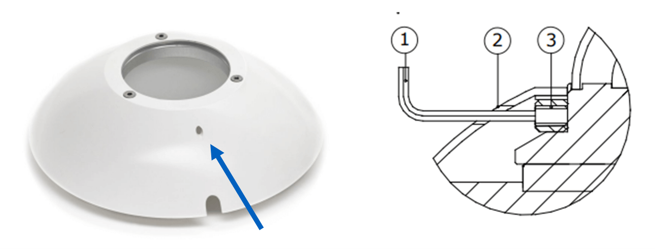
The NR01 comes with four sun screens. The down-facing sensor screens are used as ‘glare screens’ to prevent solar radiation from falling onto the sensors when the sun is at a high zenith angle. The SCR01 sun screen can be installed and removed using a 2mm hex key, as depicted in Figure 6.
Calibration
The NR01 device requires calibration to function correctly. Its four components are individually calibrated at the factory.
The pyranometers are calibrated indoors through a side-by-side comparison with a working standard. This working standard is a pyranometer with a known sensitivity that is calibrated outdoors in Davos. Davos operates directly with the World Standard Group, representing the World Radiometric Reference. So, when a pyranometer is calibrated, its traceability is directly to the World Radiometric Reference.
Pyrgeometers are also calibrated indoors by a side-by-side comparison to a working standard. The working standard is calibrated outdoors to a higher level working standard. This higher-level working standard is calibrated outdoors in Davos, directly to the World Infrared Standard Group. So, its traceability also relates directly to this standard group.
Data logger to calculate net radiation quantities
The data logger is a device that stores voltage and resistance measurements and uses this data to calculate the actual net radiation quantities.
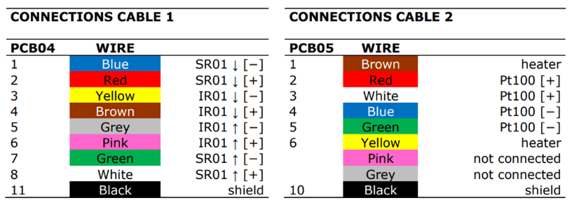
The NR01 comes with two cables, each containing eight wires and a shield. Cable 1 contains the four main centres, which should be connected to voltmeters. Cable 2 contains the Pt100 temperature sensor, which should be connected to a resistance meter, and the heater, which should be connected to a 12 VDC power supply.
Maintenance
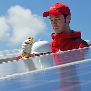
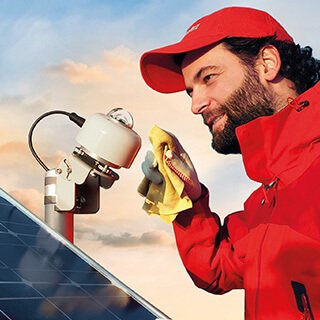
Once the sunlight measuring device is installed and set up, it is important to maintain it properly to ensure reliable data over a long period. To obtain accurate measurements, keeping the domes and windows of the instrument clean is important. Dirt or moisture on these components can negatively affect the data, so we recommend cleaning them at least twice a week. A soft cloth can be used to clean the glass domes, silicon windows, and down-facing sensors. Persistent stains can be removed with soapy water or alcohol.
Recalibrating this instrument every two years is recommended, as the sensitivity value may degrade over time. There are two ways to perform recalibration: sending the instrument back to the factory or a dedicated calibration institute or making a side-by-side comparison with a higher standard or recently calibrated instrument in the field.
Quality control your data
To ensure high-quality measurements, it is important to control the quality of your data. This involves critically examining the data you generate to ensure that you measure sensible results. One effective method is to compare your measured values with those you expect from literature or models. For instance, you can compare the temperature measurements of an instrument with the ambient temperature to ensure that the device is within reasonable limits. Several clear sky models are available for global solar radiation that can be useful for comparison purposes.
Over the years, automated quality control tests have been developed for these instruments. For example, the Baseline Surface Radiation Network (BSRN) QC test is a powerful tool that provides physically possible limits or rare limits to your quantities and comparisons between different measurements to check if they make sense.
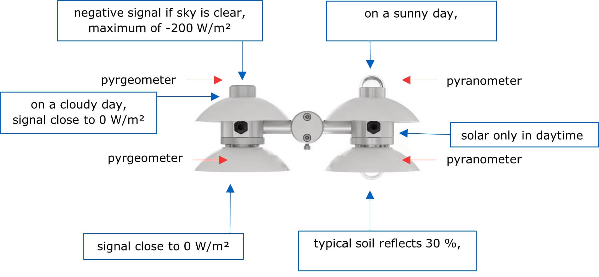
You can also check the validity of your signals by comparing them to expected signals. For instance, on a sunny day, the maximum global solar radiation that a pyranometer can measure is 1500 W/m2. Typically, soil reflects about 30 % of the incoming shortwave radiation, while snow can reflect up to 100 %. Lastly, pyranometers should only detect a signal during the daytime since they measure shortwave radiation.
Regarding longwave radiation, the up-facing pyrgeometer should measure a negative signal since the sunlight measuring device is looking at the sky, which should be colder than the surface. Especially on a clear day, you can expect a signal of at least -200 W/m2. The down-facing pyrgeometer, on the other hand, should have a signal close to 0 W/m2 because its temperature is usually similar to the surface temperature.
Conclusion
Understanding the energy balance at the surface of the earth is crucial to better understand meteorological processes. The NR01 net radiometer plays a vital role in studying this balance, as it measures shortwave and longwave radiation with its two SR01 pyranometers, IR01 pyrgeometers, Pt100 temperature sensor, and a built-in heater.
Once a representative measurement site is selected, the NR01 must be installed. It must be regularly cleaned and calibrated. The collected data can be compared and used as input for improved modelling.
Related to How to measure net radiation: a practical guide
Solar energy meters: why use them in measuring solar energy?
Solar monitoring: using pyranometers in PV monitoring